Ray Tracing 009Diffuse Materials
 Back to Anti-Aliasing
 Back to Ray Tracing
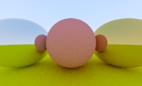 Continue with Metal
Summary
- Introduction to diffuse materials and the behavior of light rays when they hit the surface of a diffuse object.
- Brief introduction to gamma-correction.
- Handling "Shadow Acne" due to floating point approximation errors.
- Experiments attempting to further speed up Javascript rendering.
The next few chapters will be about materials. The first material is a simple diffuse or matte material.
Diffuse objects take on the color of their surroundings, but they modulate it with their own color.
And light that reflects off a diffuse surface gets reflected in a random direction. If there are two diffuse objects touching each other you can end up with rays that reflect off the first object and never touch the second, or rays that reflect off the first, then the second before they move away from the objects. You could also see rays that relect off the first, then the second to hit the first again before they leave the objects.
Rays may also get absorbed rather than reflected. The darker the surface, the more likely it gets absorbed.
One of the simplest ways to accomplish this is to place a unit sphere tangent to the hitpoint P, pick a random point S in that unit sphere, and then send the ray from the hitpoint P through S.

The unit sphere has its center at (P+N). To find the random point S on the unit sphere we can use a rejection method. Basically, I pick a random point in a unit cube with x, y, z ranging from -1 to +1. If the point is outside of the sphere, we reject it and try again until we find a point that's inside the sphere. This is pretty easy:
vec3 random_in_unit_sphere() {
  vec3 p;
  do {
    p = 2.0 * vec3(
      random_double(),
      random_double(),
      random_double()
    ) - vec3(1,1,1);
  } while (p.squared_length() >= 1.0);
  return p;
}
Squared_length() returns the equation for a sphere. For a unit sphere the radius could be 1.0. If the squared length is larger than that we are somewhere in the space between the unit sphere and the unit cube, so we repeat with a new set of random numbers.
Next we update the color() method to use the random point in the unit sphere. Here we absorb half the energy and reflect the other half. To process the color for the reflected ray we call color() for a ray from hit point P in the direction of the random point. If a ray gets reflected several times the last rays will only affect a fraction of the color.
if (world->hit(r, 0.0, INFINITY, rec)) {
[HL]
vec3 target = rec.p + rec.normal + random_in_unit_sphere();
return 0.5 * color( ray(rec.p, target - rec.p), world );
[/HL]
}
else {
vec3 unit_direction = unit_vector(r.direction());
float t = 0.5 * (unit_direction.y() + 1.0);
return (1.0-t) * vec3(1.0, 1.0, 1.0) + t*vec3(0.5, 0.7, 1.0);
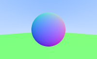
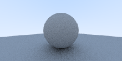
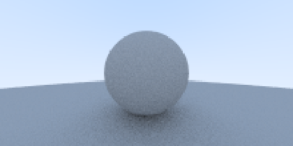
}This produces the following image:
This picture appears darker than it's supposed to be. This is because almost all image viewers assume that the image is gamma-corrected, where the 0-1 values have been transformed before they were stored in a byte.
The first book doesn't go into further explanations, but states that we need to be aware of it. Gamma-correction is an adjustment made to account for the sensitity of the eyes toward certain levels of brightness/grey. Our eyes are much more sensitive to changes in dark tones than we are to similar changes to bright tones. To use the available number range to store color values, we try to use most of the range for the colors we're more sensitive to, and less for the colors we may not easily spot a difference.
The solution in the book was to use "gamma 2". In this first approximation we simply raise the color to the power or in this case 1/2 which is just a square root.
col /= float(ns);
col = vec3( sqrt(col[0]), sqrt(col[1]), sqrt(col[2]) );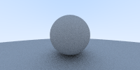
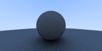
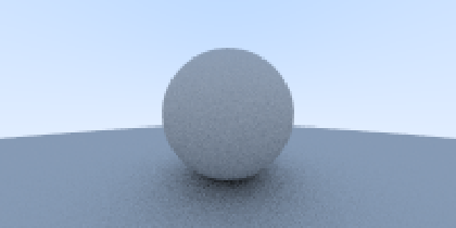
There is another small problem in this picture. Some of the reflected rays are not reflected at exactly t=0, but t=+/-0000001 due to floating point approximation errors. This can be fixed by increasing t_min a little, for example: 0.001.
if (world->hit(r, 0.001, INFINITY, rec)) { ...Here's a before/after comparison. Move the slider to the left to see the image with "shadow acne" and to the right to see the fixed image.
Room for Optimizations?
When I updated my Javascript ray tracer implementation I noticed in the following block that we add rec.normal and the random unit sphere point to the hit point to define the target, but then we subtract it from the target again:
if (world->hit(r, 0.0, INFINITY, rec)) {
  vec3 target = rec.p + rec.normal + random_in_unit_sphere();
  return 0.5 * color( ray(rec.p, target - rec.p), world );
}
Removing rec.p should be a safe change that doesn't change the output at all. We may write:
if (world->hit(r, 0.0, INFINITY, rec)) {
  vec3 target = rec.normal + random_in_unit_sphere();
  return 0.5 * color( ray(rec.p, target), world );
}
This makes sense, because the ray still starts at hit point rec.p and the second parameter in the ray() constructor is B, the ray's direction.
Since we're only interested in direction, and the point in the sphere is randomized anyway, do we need rec.normal? Let's see, move the slider to the right to see what happens if rec.normal is eliminated:
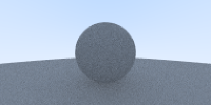
Well, yes, we do need it! Without the surface normals we still get something that resembles a sphere with a hint of a shadow, but it's flatter, less defined, and much darker. It makes sense, since normals describe the shape of the surface for light that hits it. However, I'm not very clear why the difference is so strong. I'd expect some difference, but to a lesser degree.
I mean, if you add random numbers to a normal, shouldn't the result be just as random? I'm guessing that without the normal, those random numbers are distributed all around that unit sphere, including the areas that shouldn't get so much attention. The normal helps reduce the influence in areas that should receive less random numbers and amplify those that should receive more, depending on where we are in 3D space. That might explain why there still is a sphere shape, but overall much flatter.
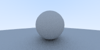
The other idea for a possible optimization was to use keep unit-cube and dismiss the extra checks to to see if the point happened to be in the unit-sphere. The loop to find points in the unit-sphere might add quite a bit of time to the computation. It could finish in the first or second iteration, but it could also take many more iterations. Here's what it looks like if I use a unit-cube instead of a sphere (move slider to the right to reveal the test image):
There are some noticeable differences, but they are not as bad as the previous attempt to optimize the performance. If the image doesn't have to be super-accurate... who knows, this may be a way to squeeze out some time.
Here's also my Javascript rendering:
Loading...